 Functional Netlist ECO
An in-depth look at functional netlist ECO.
Functional Netlist ECOConsider a functional ECO that leaves GOF's DFT design rule checker reporting ERROR_MULTI_PATHS at a flop. The code identifies multiple paths in the scan chain under the configured test conditions. It does not, by itself, explain which connection caused the violation or what the repair should preserve.
That is the moment to move from the report into the circuit. In GOF Debug, the schematic starts at the flagged instance and grows only along the paths you choose to inspect. Once the cause is clear, GOF's GUI ECO mode lets you make the change in that same schematic.
Load the netlist revision used for the DRC run and its cell libraries. A failed DFT check may name a flop buried under a long hierarchy path: copy that full instance name from the report, press Ctrl+g in GofViewer, and load the instance into GofTrace. From its input and output pins, expand drivers and loads with the middle mouse button. The schematic reveals the local circuit without drawing unrelated gates.
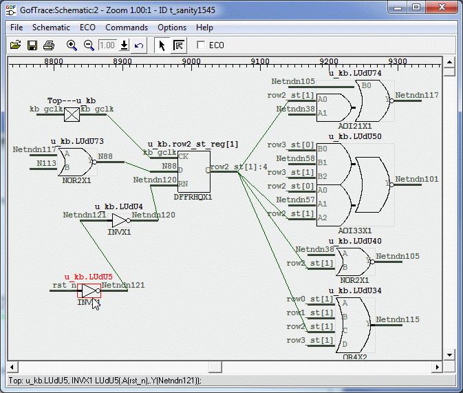
This matters because the error location and the root cause are often different. A rule may fail at a downstream flop, while the offending gate was inserted one connection upstream. On the schematic you can follow the exact pin-to-pin path and ask a more useful question: what is driving this flop in functional mode, and what drives it during scan shift?
Interpret those paths using the DRC run's test-mode settings, including scan enable, clocks, and resets. Confirm that the setup describes the intended test operation before deciding that the netlist needs a repair.
The GOF manual's DFT DRC example starts with two back-to-back flops. FLOP_A has scan-input and scan-enable pins. FLOP_B has no separate scan input: in this arrangement, its D pin receives the data shifted from FLOP_A/Q.
A functional ECO inserts a NAND gate between FLOP_A/Q and FLOP_B/D. The NAND implements the intended functional change, but it also introduces another signal into the path used for shifting. In this documented example, GOF's DFT DRC reports ERROR_MULTI_PATHS.
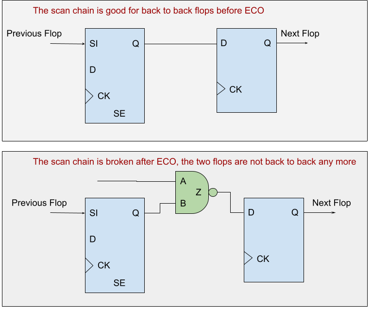
Trace from FLOP_B/D through the NAND and inspect both inputs. Then follow the scan control connections: scan enable controls FLOP_A, but there is no scan-controlled bypass around the new NAND. During shifting, FLOP_B/D now receives the NAND result instead of FLOP_A/Q directly. That explains how the functional ECO disrupted the original shift path and identifies the connection to repair.
Follow the reported violation back to the connection that changed, then check what that connection must do in each mode.
One documented repair is to insert a MUX before FLOP_B/D. Its IN0 receives the NAND result; its IN1 receives FLOP_A/Q. With SCAN_SHIFT=0, the MUX selects the intended functional logic. With SCAN_SHIFT=1, it selects the direct flop-to-flop path.
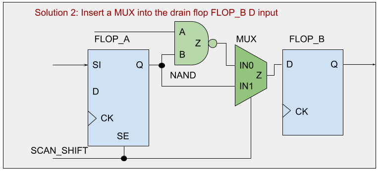
The alternative is to replace FLOP_B with an appropriate scan flop, keeping the NAND result on D, connecting SI to FLOP_A/Q, and connecting SE to the scan-shift control. Both repairs separate functional data from shift data; the choice depends on the design's DFT architecture and implementation constraints.
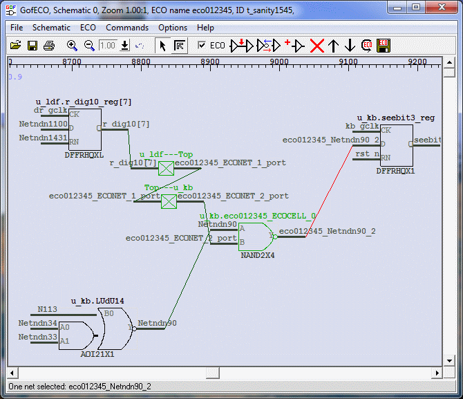
GOF supports these fixes in GUI ECO and script mode. For the MUX repair, enable ECO mode in the schematic, place the selected library cell, and connect its data, select, and output pins as shown above. You can inspect the edited circuit immediately in the same view. This is the on-the-fly ECO workflow: diagnose the connection, change it, and review the resulting connectivity while the circuit is still in front of you.
The separate GUI example below illustrates the gate-placement and connection controls with a NAND insertion.
Save the updated netlist or export and apply the ECO script, then verify the resulting netlist. Rerun DFT DRC and scan checks under the intended test conditions. Separately, run functional equivalence against the reference that includes the intended functional change, with scan shift disabled and the appropriate functional-mode constraints. Complete the project's downstream timing, physical, and sign-off checks before accepting the repair.
Ctrl+g.The advantage is continuity. The schematic you use to understand the violation is also the workspace where you make and inspect the ECO. The instance, its surrounding logic, and the changed connections stay in view as you turn a DRC finding into a concrete repair ready for verification.